 http://powersportsoutletstore.com/product/33-3910
[strike:3eovo2fv]About 57 dollars after shipping. [/strike:3eovo2fv] This is not a fancy tach. just a plain and simple 8K RPM tach.
Update 08/17/10: Powersportsoutletstore.com has entered the dustbin of history.
I found what appears to be the same tach at BKrider for $39.99 + $8 and change shipping.
Additional parts needed for install
- Zip ties as needed.
Tools required:
- Soldering iron and solder.
- Socket set preferribly with extensions.
Overview:
This is a quick installation guide for the above tachometer. Installation should take about 1/2 hour. All wiring is done directly to the ignition coil for the simplest wiring. If you want to get creative there are other way you can do it. There are two wires that attache to the ignition coil with female blade connectors. The one on the right side of the bike is the negative and the one on the left is the + 12V. We will be soldering to these female blade connectors and using the mounting bolt of the ignition coil as a grounding point.
Step 1 Mounting:
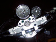
- Use the conviently located bolt shown in the picture for attaching the tach with the included bracket.
- Remove the nut and washer
- Slide tach over bolt
- Put washer and nut back on.
- If you don't like that the tach is at an angle you could easily make a custom bracket so it is at the same angle as the spedometer.
Step 2 Wiring:
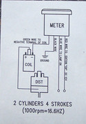
- This wiring diagram was the only instructions that came with the tach.
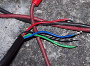
- These are the wires we have to work with.
looking at the diagram we will be connecting the green wire to the negative terminal on the coil. Since our lights come on when the key is switched to "on" we might as well have the light for the tach and the power for the tach switch on with the key as well. It just convienently happens that the +12V for the coil is also switched on when the key is in the "on" position. So we will connect the red and blue wire to the +12V terminal on the coil. The last remaining wire is the black ground wire. Also convienently there is a mounting bolt inbetween the coil terminals. We will connect the black wire to this bolt for a ground.
- Remove the gas tank (see service manual)
- Route wire from tach to the front of the ignition coil.
- Leaving a couple extra inches cut the excess lenght of wire off.
- Trim back the black outer shell a couple inches to expose individuals colored wires inside.
BE CAREFUL NOT to accidentally cut the individual wires when trimming back the outer shell!

- Disconnect the two wires with the female blade connectors from the coil and slide back rubber insulators. It may be easier to slide back the rubber insulators first to disconnect the female blade connectors.
- The wire that was connected to the left side coil terminal is red, This is the +12V. The white wire connected to the right side coil terminal is white and the negative wire.
(Note: this is on my 2000 GZ250. Other years may have different wire colors. To be sure, use a multimeter to see which one of these supplies +12V with the key switched to "on".)
EDIT NOTE: As suggested by another member I have switched to pulling the +12V from the horn. Switch the key to the on position and use a multimeter to see which of the two horn wires has +12V with a multimeter. Either way will work, but pulling +12V from the horn circuit is probably a better idea. Using the horn circuit may help with idle and idling if you have a low battery. Also my needle "bounced" less at 1000 to 1500 RPM after moving the power source to the horn circuit.
- Slide the red and blue wires from the tach up thru the rubber insulator on the red coil wire.
- Solder these wires to the back part of the female blade connector.
- Repeat the above 2 steps soldering the green wire from the tach to the white wire with the female blade connector.
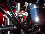
When done soldering it should look like this:
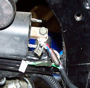
- Connect the remaining black wire to the coil's mounting bolt inbetween the terminals for the ground wire.
- Slide the rubber insulators back over the female blade connectors.
- Reconnect the blade connectors to their respective terminals on the coil.
- Finally secure the wire in place with zip ties.
This is what it should like.
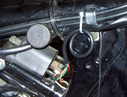
Put your gas tank back on and go for a ride :cool:
Remember to be safe and keep your eyes on the road. Don't get too distracted by your new tach.