|
|
 08-02-2007, 10:35 PM
|
#1 |
|
Senior Member
Join Date: Jun 2007
Location: Toledo, OH
Posts: 198
 |
Add a Tachometer
 http://powersportsoutletstore.com/product/33-3910 [strike:3eovo2fv]About 57 dollars after shipping. [/strike:3eovo2fv] This is not a fancy tach. just a plain and simple 8K RPM tach. Update 08/17/10: Powersportsoutletstore.com has entered the dustbin of history. I found what appears to be the same tach at BKrider for $39.99 + $8 and change shipping. Additional parts needed for install - Zip ties as needed. Tools required: - Soldering iron and solder. - Socket set preferribly with extensions. Overview: This is a quick installation guide for the above tachometer. Installation should take about 1/2 hour. All wiring is done directly to the ignition coil for the simplest wiring. If you want to get creative there are other way you can do it. There are two wires that attache to the ignition coil with female blade connectors. The one on the right side of the bike is the negative and the one on the left is the + 12V. We will be soldering to these female blade connectors and using the mounting bolt of the ignition coil as a grounding point. Step 1 Mounting: 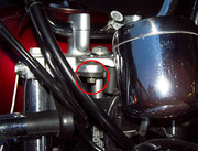 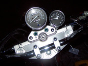 - Use the conviently located bolt shown in the picture for attaching the tach with the included bracket. - Remove the nut and washer - Slide tach over bolt - Put washer and nut back on. - If you don't like that the tach is at an angle you could easily make a custom bracket so it is at the same angle as the spedometer. Step 2 Wiring: 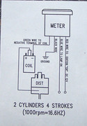 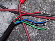 - This wiring diagram was the only instructions that came with the tach. - These are the wires we have to work with. looking at the diagram we will be connecting the green wire to the negative terminal on the coil. Since our lights come on when the key is switched to "on" we might as well have the light for the tach and the power for the tach switch on with the key as well. It just convienently happens that the +12V for the coil is also switched on when the key is in the "on" position. So we will connect the red and blue wire to the +12V terminal on the coil. The last remaining wire is the black ground wire. Also convienently there is a mounting bolt inbetween the coil terminals. We will connect the black wire to this bolt for a ground. - Remove the gas tank (see service manual) - Route wire from tach to the front of the ignition coil. - Leaving a couple extra inches cut the excess lenght of wire off. - Trim back the black outer shell a couple inches to expose individuals colored wires inside. BE CAREFUL NOT to accidentally cut the individual wires when trimming back the outer shell!  - Disconnect the two wires with the female blade connectors from the coil and slide back rubber insulators. It may be easier to slide back the rubber insulators first to disconnect the female blade connectors. - The wire that was connected to the left side coil terminal is red, This is the +12V. The white wire connected to the right side coil terminal is white and the negative wire. (Note: this is on my 2000 GZ250. Other years may have different wire colors. To be sure, use a multimeter to see which one of these supplies +12V with the key switched to "on".) EDIT NOTE: As suggested by another member I have switched to pulling the +12V from the horn. Switch the key to the on position and use a multimeter to see which of the two horn wires has +12V with a multimeter. Either way will work, but pulling +12V from the horn circuit is probably a better idea. Using the horn circuit may help with idle and idling if you have a low battery. Also my needle "bounced" less at 1000 to 1500 RPM after moving the power source to the horn circuit. - Slide the red and blue wires from the tach up thru the rubber insulator on the red coil wire. - Solder these wires to the back part of the female blade connector. - Repeat the above 2 steps soldering the green wire from the tach to the white wire with the female blade connector. When done soldering it should look like this: 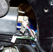 - Connect the remaining black wire to the coil's mounting bolt inbetween the terminals for the ground wire. - Slide the rubber insulators back over the female blade connectors. - Reconnect the blade connectors to their respective terminals on the coil. - Finally secure the wire in place with zip ties. This is what it should like. 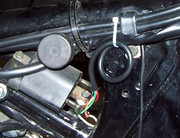 Put your gas tank back on and go for a ride :cool: Remember to be safe and keep your eyes on the road. Don't get too distracted by your new tach. Login or Register to Remove Ads Last edited by Quimrider; 09-30-2020 at 12:46 AM. Reason: Updated Image Links |

|

|
|
05-09-2016, 09:37 PM
|
#2 |
|
Senior Member
Join Date: Apr 2016
Location: Illinois
Posts: 174
|
Power for tach from headlight unused connector.
I'm looking at my options to install tach. I did go thru the schematic and found potential source of power in the front headlight that does not require modification of the wiring. There is unused power connector that appears to be for powering front parking light (not connected in US version). It is always on with ignition on, same circuit runs rear taillight (brown wire). Second wire in the connector is ground (black with white tracer). The drawback is that this is powered also when ignition switch is in parking light mode, but not too many would use this mode anyway.
Picture below is the schematic: This is part showing headlight with spare connector outlined red: This is picture of the inside of headlight: Described connector: Last edited by wacio; 05-09-2016 at 11:22 PM. |
|
|
|
|
05-20-2016, 12:16 PM
|
#4 | |
|
Senior Member
Join Date: Apr 2016
Location: Illinois
Posts: 174
|
Quote:
|
|
|
|
|
|
05-21-2016, 11:10 PM
|
#6 |
|
Senior Member

Join Date: Oct 2007
Location: HoCo, Maryland
Posts: 1,349
|
Alantf is correct about the black/white wires being 0V.
The frame is also connected to 0V. As far as I remember, I squeezed the tach's zero volt wire under a nut at the coil, to connect to the frame. You'll have to connect to the coil under the tank anyway.
__________________
2005 "Saturn Black", stock + tach Last edited by 5th_bike; 05-21-2016 at 11:14 PM. Reason: Typo, and extension. |
|
|
|
|
05-04-2017, 10:14 PM
|
#7 |
|
Senior Member
Join Date: Apr 2016
Location: Illinois
Posts: 174
|
You can try both - mine is connected to the white one.
|
|
|
|
|
05-07-2017, 01:56 PM
|
#8 | |
|
Junior Member
Join Date: Apr 2017
Posts: 2
|
Here's is how I installed it...
Since many of the photos from earlier in this thread are long gone, I figured I would document what worked for me.
I bought my tachometer from fleabay. It was $14 (best offer with free shipping). The description was “LED Motorcycle Tachometer Fit Suzuki Intruder Volusia VS 700 750 800 1400 1500" 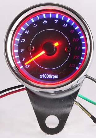 It came with no instructions and the wiring as described in the listing was quite Chinglish: Quote:
So... 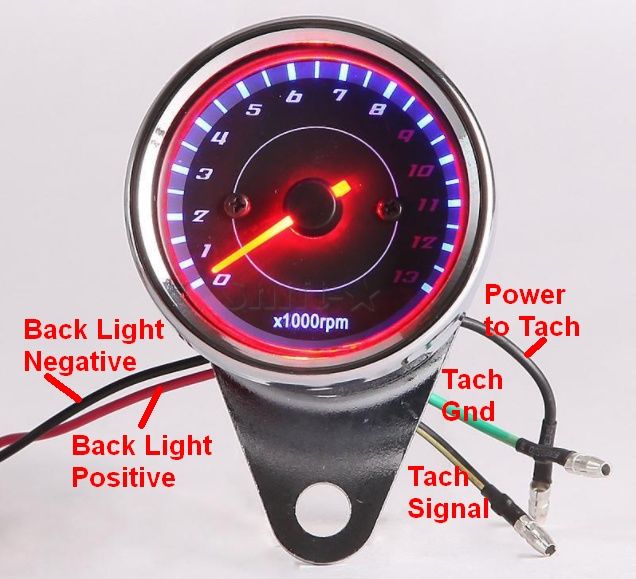 I combined and extended the long red and short black and connected them to power at the horn. (Black wire in my photo below. But you can barely see it since I pierced the black tubing and threaded it through.) I also combined and extended the long black and short green and grounded them at the coil. (Blue wire in my photo below.) I extended the yellow/black wire and connected it to the coil. (Brown wire in my photo below.) 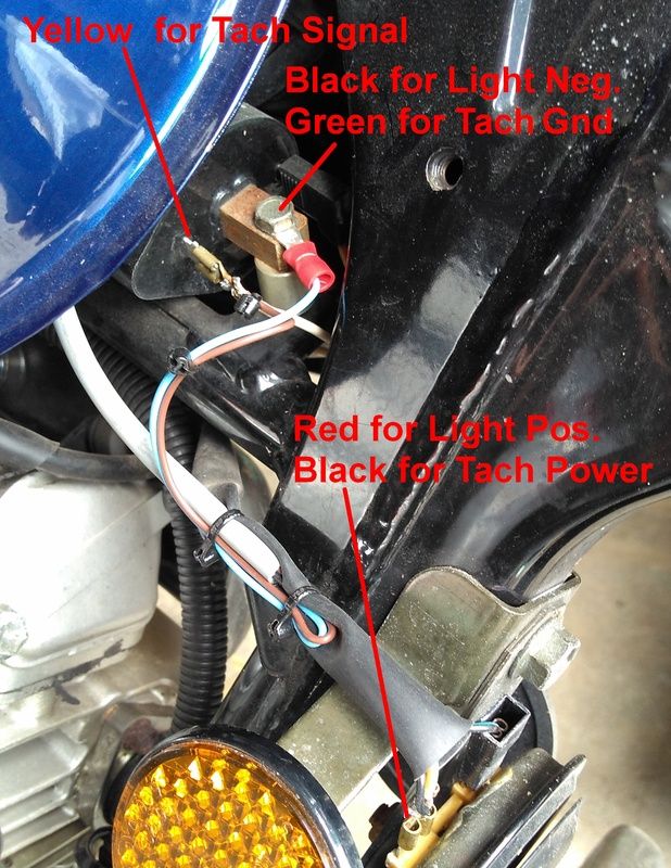 Fired it up and it worked. Tachometer reports 6800 rpm at 60 mph. A bit more than others report in this thread. The tach is somewhat on the slow side to respond; wish it was a bit faster. 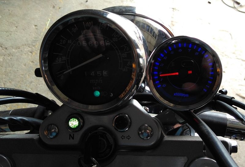
|
|
|
|
|
|
05-08-2017, 09:35 AM
|
#10 |
|
Senior Member
Join Date: Dec 2006
Location: Squamish B.C Canada
Posts: 11,409
|
Nice How To article, My Honda has a digital graph that is stupid. Round with a needle is good.
|
|
|
|
 |
|
|


 Hybrid Mode
